
BINARY DIGITAL CLOCK (BDC), YEAR 1986
1. INTRODUCTION
In the mid‑80s, one of my passions was analogue and digital electronics. I set out to design and build a digital clock with 7‑segment decimal digits. Soon I realised that I could reduce the budget and simplify construction by making the clock work in binary numbers, without needing binary‑to‑7‑segment converter circuits. The basic idea was to display the tens and units of hours, minutes, and seconds as individual numbers of at most 4 bits. It would be like a conventional digital clock, but the reading would be done directly on a binary number instead of a decimal number.
2. BINARY NUMBERS
We can imagine a digital clock with decimal numbers in this format:
tens units (hours)
tens units (minutes)
tens units (seconds)
For example:
1 9 hours
2 1 minutes
5 3 seconds
If we represent each decimal digit by a 4‑bit binary number, the clock would look like this:
0001 1001 hours
0010 0001 minutes
0101 0011 seconds
We just need to remember that the binary numbers from 0 to 9, represented with four bits, are as follows:
0000 = 0
0001 = 1
0010 = 2
0011 = 3
0100 = 4
0101 = 5
0110 = 6
0111 = 7
1000 = 8
1001 = 9
We can simply remember these 10 symbols, just as we remember the 10 decimal digits, or apply the following conversion rule:
Call each binary sign a bit, which can be "1" or "0". Bits are usually ordered and read from right to left, assigning the following numerical values (or binary weights) according to their position: 1,2,4,8,... always doubling. To convert a binary number to its decimal equivalent, multiply the weight of each bit by its value and add up the total result.
Example1: 0 0 1 1
0*8+0*4+1*2+1*1=3
Example2: 1 0 0 1
1*8+0*4+0*2+1*1=9
In general: d c b a
d*8+c*4+b*2+a*1
Read from right to left, the binary weights for a 4‑bit binary number are: 2^3 2^2 2^1 2^0
For a more general N‑bit binary number, the binary weights are 2^(N-1) 2^(N-2) ..... 2^1 2^0
But for our clock, knowing numbers up to 4 bits is enough.
3. THE BDC DISPLAY
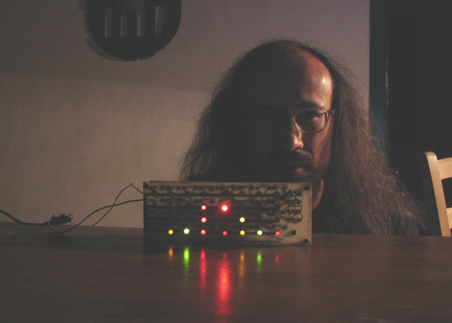
The BDC consists of 4 horizontal rows of eight LEDs. Each LED represents a bit. If the LED is on, we consider it indicates "1"; if the LED is off, it indicates "0". In each row there are two 4‑bit binary numbers. The four rightmost LEDs indicate the units, and the four leftmost LEDs indicate the tens. The top row indicates the hours (from 00 to 23), the next row the minutes (00 to 59), the next row the seconds (00 to 59), and the bottom row the hundredths of a second (00 to 99).
To make reading even easier, the LEDs are colour‑coded as follows:
red corresponds to the rightmost digit, with binary weight 1
green corresponds to the digit to its left, with binary weight 2
yellow corresponds to the digit to its left, with binary weight 4
blue corresponds to the digit to its left, with binary weight 8
Thus, just by looking at the colours we can know the number, and we add the colours within the binary number.
Of course, to read the binary clock you don’t need to know how to add! You only need to remember the 10 binary symbols or colour combinations that correspond to the decimal digits from 0 to 9.
Red always means 1,
green always means 2,
yellow always means 4,
blue always means 8,
red and green always mean 1+2=3,
green and yellow always mean 2+4=6,
and so on... Here is an example:
• • • •
• • • •
= 2 3 hours
• • • •
• • • •
= 5 6 minutes
• • • •
• • • •
= 3 9 seconds
• • • •
• • • •
= 9 7 hundredths
Recall:
• • • • = 0
• • • • = 1
• • • • = 2
• • • • = 3
• • • • = 4
• • • • = 5
• • • • = 6
• • • • = 7
• • • • = 8
• • • • = 9
It’s easy! :)
4. ELECTRONIC CIRCUIT
5. PRINTED CIRCUIT BOARD
6. APPLICATION TO PUBLIC CLOCKS